Inspect Call Frame
Purpose
Debuggers often need to view and modify the state of frame on the call frame stack. To be able to view or modify a frame that is not on the top of the call frame stack, the debugger must virtually unwind the stack of call frame util it finds the frame of interest. Virtually Unwind means it has the logic effect of returning from the current subroutine to its predecessor, but it can still rewind the stack back to the state it was in before it attempted to unwind it, just thinking gdb commands like bt, frame $n, info frame.
Dwarf v2 provides a way to describe the call frame information which is stored in section .debug_frame, and the basic idea of .debug_frame is to allow debuggers to figure out how to unwind frames, i.e., how to restore the previous frame from any instruction executing using the current frame.
For Example, consider the following assembly (with C code inline – objdump -S):
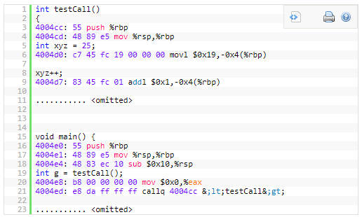
For example, when we are inside testCall (i.e. from 4004cc onward), at every instruction, the .debug_frame information should allow us to restore all registers (such as rbp, rsp, eax etc.) to their previous status in the caller’s frame (here the caller is main). This is done by keeping a table structure that keeps track of all the changes that happens with each register for every line of assembly.
CIE & FDE
As is mentioned above, we need keeping a table structure that keeps track of all the changes that happens with each register for every line of assembly.
Table Structure
Dwarf supports virtual unwinding by defining an architecture independent basis for recording how procedures save and restore registers throughout their lifetimes. The basis must be augmented on some machines with specific information that is defined by either an architecture specific ABI authoring committee, a hardware vendor, or a compiler producer. The body defining a specific augmentation is referred to below as the augmenter.
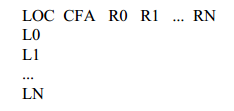
In this table:
LOC, it’s the address of assembly (for example 4004cc), possible values are the address of each instruction.
CFA, it’s the call frame address, which uses a register and an offset to calculate the CFA.
R0~RN: they’re the registers that the particular architecture has, they record whether the registers’ values has been changed and how the value is changed.
Possible values are:
- Undefined(u): has no value in previous frame, it’s not preserved by a callee.
- Same(s): hasn’t been modified from previous frame, it’s not preserved by the callee, but the callee doesn’t modify it.
- Offset(N): previous value of this register is stored at the address CFA+N where CFA is the current CFA value and N is a signed offset.
- Register(R): previous value of this register is stored at the register number R.
- Architectural: the rule is defined externally to this specification by the augmenter.
In essence, the .debug_frame section and its corresponding cryptic tags are used to help the user construct such table.
Build Table
Example
Take following code as an example:
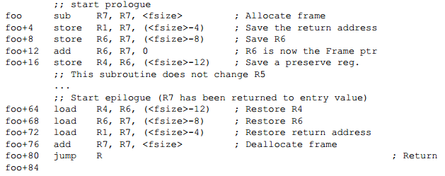
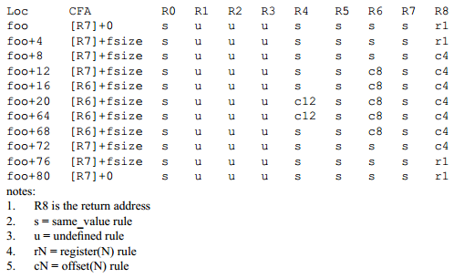
The .debug_frame can be used to generate following table:
CIE helps building the 1st row in CFI
In section .debug_frame, each compilation unit has a single Common Information Entry (CIE), CIE describes how to built the first row in this table by the initial instructions included in this CIE, for example, cie+13~cie+35 can be used for building the first row foo [R7]+0 s u u u s s s s r1.
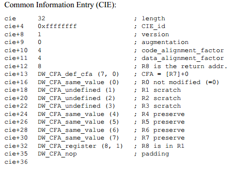
A CIE holds information that is shared among many Frame Descriptions. There is at least one CIE in every non-empty .debug_frame section. Often, a compilation unit has a single CIE entry, which may contains a slice of FDE entries. A CIE has the following fields: length, CIE_id, version, augmentation, code_alignment_factor, data_alignment_factor, return_address_register, initial_instructions, padding.
This list shows how to construct the table structure. Read this in order:
- The CIE structure is 32 in length
- This CIE has no augmentation (cie+9 = 0)
- Code alignment factor is 4, so all location advancement needs /4
- Data alignment factor is 4, so all offset advancement needs *4
- The next one (cie+12) is the Register that holds the return address initially
- The rest of the cie structure can either be all nop to pad to the correct length, or they can be definitions to set up the first row of the table. See that the above example sets up the 1st row correctly
FDEs help building following rows of CFI
Once the table structure is set up, FDE describe how each new row is constructed. There is an FDE per function per compilation unit. (Usually only 1 CIE for each CU).
Each CIE has a slice of FDEs, among which each FDE has a pointer to this CIE. These FDEs can be used for building the following rows in this table by the included instructions in this FDE.
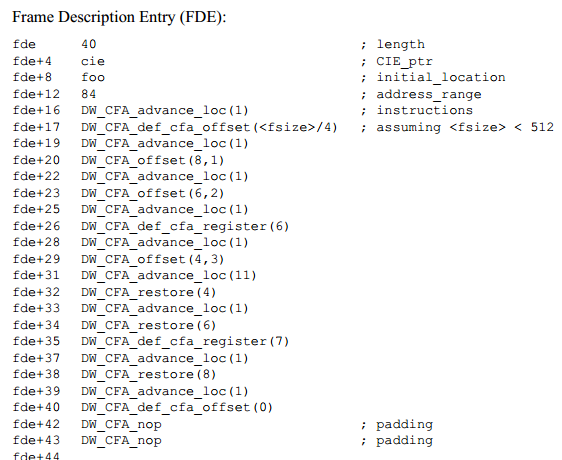
A FDE holds information about a call frame, it has the following fields: length, CIE_pointer, initial_location, address_range, instructions.
The field initial_location refers to the address of the first assembly in this FDE, the address_range refers to the number of bytes of Dwarf DWCFA... instructions used for recreating the table row. When specifying a PC, we can use this expression (PC - fde.initial_location < fde.address_range) to check whether this PC (instruction address) is within the range of this FDE. Actually we need to traverse the FDEs in the CIE to check which FDE covers the PC.
- Columns of new rows are initialized to the previous row first whenever a new row is added
- FDE+16, advance_loc(1) means insert a new row in the table
- FDE+17, def_cfa_offset means that the CFA column now has an offset at fsize/4 (4 being the data_alignment)
- FDE+18, add new row
- FDE+19, CFA_offset(8, 1), this means that register 8 is now stored at offset of 1*4 from CFA
- FDE+38, register 8 is restored to the initial value (first row of the table)
That’s it! This basically covers .debug_frame.
Ref: http://ucla.jamesyxu.com/?p=231
Call Frame Instructions
DW_CFA_advance_loc(delta), advance delta * code_alignment_factor,
DW_CFA_def_cfa_register(R), takes a single unsigned LEB128 argument R representing a register number. The required action is to define the current CFA rule to use the provided register (but to keep the old offset).
DW_CFA_def_cfa_offset(N), takes a single unsigned LEB128 argument N representing an offset. The required action is to define the current CFA rule to use the provided offset (but to keep the old register).
DW_CFA_offset(R, N), takes R as register number and N as offset to CFA, this create a offset(N) rule on register numbered R.
DW_CFA_restore(R), takes R as register number, it applies the rule assigned by CIE to R before to this register again in this new row.
some of instructions mentioned above play an effect on following generated row, for example, DW_CFA_restore, etc.
According to this instructions stored in CIE or FDEs, we can know how to build the table structure.
Calc ReturnAddress
How to calculate the ReturnAddress given any instruction in current frame?
Calculate the CFA according to the table mentioned above.
CFA is specified by a register (golang uses RSP) and an offset, because Dwarf instruction DWCFA... cannot affect RSP’s value, so when PC of instruction is specified, we can directly execute instructions in the single FDE covering this PC to get the CFA.
Remark: If we want get other registers’ values, we must execute all the predessesor FDEs’ instructions, then excute the FDE’s instructions which covering this PC. Only by this, other registers’ values can be affected rightly.
Find the registered which holds the return address
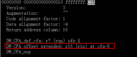
Confirm which register holds the return address by CIE.return_address_register, this register maybe a virtual one (not an actual machine register), such as "CFA - 8" used in golang’s CIE, which refers to a memory address, then we can use ptrace to peek the data stored in this memory address, this is the return address.
Here is an golang CIE sample, DW_CFA_offset_extended: r16 (rip) at cfa-8, it defines that register numbered 16 is not an actual machine register, actually it points to a memory unit with address cfa-8.
CFA is short for Canonical Frame Address or Caller Frame Address rather than ReturnAddress. Here’s an issue which describes this point: https://github.com/derekparker/delve/issues/1181.
Also, you can checkout this repo to validate this issue: https://github.com/hitzhangjie/golang-debugger at revision <9097961>.